

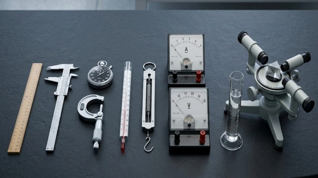
Introduction
Every physics experiment begins the same way — with a measurement. The quality of everything that follows, every calculation, every conclusion, every result reported in a lab notebook, depends entirely on how well that first step was done. And how well it is done depends on knowing the instrument in your hand — not just its name, but its working principle, its least count, how to read it correctly and where it fits relative to other instruments in terms of precision.
Physics students encounter a surprisingly wide range of measuring instruments across Class 11, Class 12 and competitive exam practical papers. Some are mechanical, some electrical, some optical. Each one has a specific purpose, a specific range and a specific level of precision it is capable of delivering. Knowing all of them — properly, not just by name — is what makes the difference between a student who is confident in the lab and one who is not.
This article covers ten instruments every physics student should know well. Each entry explains the working principle, the least count, how to read it, what it is used for and the specific mistakes students most commonly make with it.
1. Metre Scale (Ruler)
Working Principle
The metre scale is the most fundamental length-measuring instrument. It works on direct comparison — the length of the object is compared against the calibrated graduations on the scale.
Least Count and Range
- Least count: 1 mm (for a standard millimetre-graduated ruler)
- Range: 0 to 100 cm (standard metre ruler) or 0 to 30 cm (standard lab ruler)
- Estimated reading: 0.5 mm with practice, by estimating between the 1 mm divisions
How to Read It
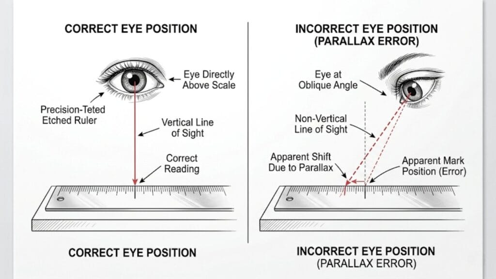
Place the zero mark (not the physical end of the ruler, which may be worn) against one end of the object. Read the scale at the other end with your eye directly above the mark — never at an angle, which introduces parallax error. For maximum accuracy, use the middle portion of the ruler rather than the ends, which may be damaged.
What It Is Used For
Measuring lengths, widths, heights and distances in the centimetre-to-metre range. Used in virtually every mechanics experiment involving length — pendulum lengths, spring extensions, track distances and object dimensions.
Common Mistakes
- Using the physical end of the ruler as zero when it does not align with the zero graduation
- Reading from an angle, causing parallax error
- Tilting the ruler at an angle to the object — a tilted ruler gives a reading longer than the true length (cosine error)
2. Vernier Caliper
Working Principle
The Vernier caliper uses a secondary sliding scale — the Vernier scale — to subdivide the smallest division of the main scale. The Vernier scale is deliberately made slightly shorter than an equivalent number of main scale divisions. This small difference, called the least count, is what allows sub-millimetre precision.
The key idea: only one Vernier division will align precisely with a main scale division at any given jaw position. That coinciding division tells you the fractional part of the reading.
Least Count and Range
\[ \text{LC} = 1\text{ MSD} – 1\text{ VSD} = \frac{\text{Value of 1 MSD}}{\text{Number of Vernier divisions}} \]
- Standard LC: 0.1 mm (10-division Vernier) or 0.01 cm
- Range: 0 to 15 cm (standard lab model); some go to 30 cm
How to Read It
Step 1: Read the main scale — the last complete millimetre mark to the left of the Vernier zero.
Step 2: Find the Vernier scale division that aligns most clearly with any main scale division. This is the Vernier Scale Reading (VSR).
Step 3: \[ \text{Total Reading} = \text{MSR} + (\text{VSR} \times \text{LC}) – \text{Zero Error} \]
What It Is Used For
Measuring external dimensions (diameter of a cylinder, length of a block), internal dimensions (inner diameter of a hollow tube) and depths. Precision of 0.1 mm makes it suitable for objects where a ruler is insufficient but a screw gauge’s range is too small.
Common Mistakes
- Not checking for zero error before the first reading
- Reading the Vernier scale at an angle instead of straight on
- Forgetting that the VSR is a count of divisions — a pure number — not a measurement in mm
- Tilting the jaws during measurement, giving a reading larger than the true dimension
Learn more about Least Count of Vernier Caliper and Screw Gauge: Formula & Calculation
3. Screw Gauge (Micrometer Screw Gauge)
Working Principle
The screw gauge uses the mechanical principle of a finely threaded screw to convert circular motion into linear displacement. When the thimble rotates by one complete revolution, the spindle advances by a fixed linear distance called the pitch. By dividing that pitch into many equal circular divisions on the thimble, very small linear distances can be read with precision.
Least Count and Range
\[ \text{Pitch} = \frac{\text{Distance moved in N rotations}}{N} \]
\[ \text{LC} = \frac{\text{Pitch}}{\text{Number of circular scale divisions}} \]
- Standard pitch: 0.5 mm
- Standard LC: 0.5 mm ÷ 50 = 0.01 mm
- Range: 0 to 25 mm (standard lab model)
How to Read It
Step 1 (Sleeve reading): Read the last complete mm mark visible on the sleeve. Check whether the 0.5 mm graduation is also visible — if yes, add 0.5 mm.
Step 2 (Thimble reading): Note the circular scale division aligned with the reference line. Multiply by LC.
Step 3: \[ \text{Total Reading} = \text{Sleeve Reading} + (\text{CSR} \times \text{LC}) – \text{Zero Error} \]
What It Is Used For
Measuring small lengths with high precision — wire diameter, glass plate thickness, ball bearing diameter. The 0.01 mm precision makes it ten times more precise than a standard Vernier caliper, though its range is much smaller.
Common Mistakes
- Missing the 0.5 mm graduation on the sleeve — gives an answer exactly 0.5 mm too low
- Using the thimble instead of the ratchet stop to close the spindle — inconsistent pressure causes variable readings
- Applying zero error correction in the wrong direction
Learn more about How to Read a Measuring Instrument Correctly: Tips for Physics Lab
4. Stopwatch
Working Principle
A stopwatch measures time intervals. Mechanical stopwatches use a spring-driven oscillating mechanism — the spring drives a gear train that moves the hands. Digital stopwatches use a quartz crystal oscillator whose vibration frequency is precisely known, with an electronic counter tracking the oscillations.
Least Count and Range
- Mechanical stopwatch LC: 0.1 s (some read to 0.2 s)
- Digital stopwatch LC: 0.01 s
- Range: Typically 0 to 30 minutes (for lab stopwatches)
How to Read It
For mechanical stopwatches, read the minute hand on the outer scale and the second hand on the inner scale. Add them together.
For digital stopwatches, read the digital display directly. The display format is typically MM:SS.ss (minutes, seconds, hundredths).
What It Is Used For
Timing experiments — pendulum oscillations, projectile flight times, cooling curves in calorimetry, velocity measurements over known distances. It is the primary time-measuring instrument in all Class 11 and Class 12 practical experiments involving motion, oscillation, or thermal processes.
Common Mistakes
- Reaction time error: The human reaction time (approximately 0.1 to 0.3 seconds) adds a systematic error to all stopwatch measurements. This is irreducible for a single measurement but partially averages out when timing multiple oscillations.
- Timing single oscillations instead of ten or twenty — amplifies the reaction time error. Always time n oscillations and divide by n to get the period.
- Not resetting the stopwatch to zero before starting
5. Thermometer
Working Principle
A mercury or alcohol thermometer works on the principle of thermal expansion. When the thermometer is placed in contact with a substance, heat flows until thermal equilibrium is reached. The liquid in the thermometer expands or contracts with temperature change and this volume change is visible as a change in column height against a calibrated scale.
Clinical and digital thermometers use different operating principles — bimetallic strips, resistance temperature detectors, or infrared sensors — but the mercury-in-glass model is the standard laboratory instrument.
Least Count and Range
- Standard lab thermometer LC: 1°C or 0.5°C
- Range: Typically −10°C to 110°C for standard lab models
- Clinical thermometer LC: 0.1°C, Range: 35°C to 42°C
How to Read It
- Allow the thermometer to reach thermal equilibrium in the substance being measured — do not read it immediately upon immersion.
- Read the scale with the thermometer still inside the liquid. The column shifts as soon as it is removed from the thermal environment.
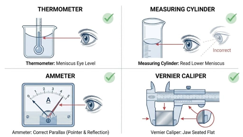
- Hold the thermometer vertically and position the eye exactly level with the top of the mercury column. Reading from above or below introduces parallax.
- For mercury: read the top of the meniscus. For coloured alcohol: also read the top of the column.
What It Is Used For
Calorimetry experiments (specific heat capacity, latent heat), thermal expansion experiments, cooling and heating rate studies and boiling/melting point determination.
Common Mistakes
- Reading the thermometer after removing it from the liquid — the column shifts immediately
- Not waiting for thermal equilibrium — reading too early gives the thermometer’s initial temperature, not the substance’s temperature
- Eye not level with the meniscus, causing parallax
6. Spring Balance
Working Principle
A spring balance measures force (most commonly weight) by using Hooke’s Law: the extension of a spring is directly proportional to the applied force, provided the elastic limit is not exceeded.
\[ F = kx \]
Where \( F \) is the force, \( k \) is the spring constant and \( x \) is the extension. The scale is calibrated in Newtons (or sometimes grams-force) based on this proportionality.
Least Count and Range
- Least count: Varies by model — typically 0.1 N to 1 N
- Range: Depends on the spring — commonly 0 to 5 N, 0 to 10 N, 0 to 20 N, or 0 to 50 N for lab models
How to Read It
- Hang the spring balance vertically from a fixed support. Never hold it horizontally or at an angle when reading — gravity must act along the spring axis.
- Allow the pointer to settle completely before reading.
- Add the load and wait for oscillations to damp out fully.
- Read with the eye level with the pointer, perpendicular to the scale face.
What It Is Used For
Measuring weight and gravitational force in dynamics experiments, measuring tension in strings, checking Hooke’s Law directly, measuring friction forces on a horizontal surface.
Common Mistakes
- Reading before the pointer stops oscillating — gives a value anywhere in the oscillation range
- Exceeding the maximum rated load — permanently deforms the spring and destroys calibration
- Not zeroing before adding the load — many spring balances have a small zero adjustment screw
7. Ammeter
Working Principle
An ammeter measures electric current flowing through a circuit. In a moving-coil galvanometer-based ammeter, current through a coil in a magnetic field creates a torque that deflects a pointer. The deflection angle is proportional to the current. A low-resistance shunt is connected in parallel with the galvanometer to allow it to measure larger currents without damage.
A digital ammeter uses an analog-to-digital converter to display current directly on a numerical readout.
Least Count and Range
\[ \text{LC} = \frac{\text{Full scale range}}{\text{Number of scale divisions}} \]
- Typical ranges: 0 to 100 mA, 0 to 1 A, 0 to 5 A (depending on model)
- Connection: Always in series with the circuit — never in parallel
How to Read It
- Select the appropriate range before connecting — start with the highest range and reduce if the deflection is too small.
- Connect in series. Connecting in parallel short-circuits the circuit and can destroy the ammeter instantly.
- Eliminate parallax using the mirror strip — align the pointer with its reflection before reading.
- Read the correct scale corresponding to the selected range terminal.
What It Is Used For
All circuits experiments — Ohm’s Law verification, Kirchhoff’s Laws, measuring current through resistors, diode characteristics, transistor biasing, potentiometer experiments.
Common Mistakes
- Connecting in parallel instead of series — this creates a short circuit
- Reading the wrong scale when the instrument has multiple range scales
- Not using the mirror strip, causing parallax error
- Selecting too low a range, causing the pointer to slam past full deflection
8. Voltmeter
Working Principle
A voltmeter measures the potential difference between two points in a circuit. It is essentially a high-resistance galvanometer — the high resistance ensures that almost no current flows through the voltmeter itself, so it does not disturb the circuit being measured. A multiplier resistor is connected in series with the galvanometer to extend the voltage range.
Digital voltmeters use high-impedance electronic sensing circuits.
Least Count and Range
\[ \text{LC} = \frac{\text{Full scale range}}{\text{Number of scale divisions}} \]
- Typical ranges: 0 to 1.5 V, 0 to 3 V, 0 to 15 V (depending on model)
- Connection: Always in parallel with the component across which potential difference is to be measured
How to Read It
- Select the range above your expected measurement.
- Connect in parallel — positive terminal to the higher potential point.
- Use the mirror strip to eliminate parallax.
- Read the scale corresponding to the terminal used.
What It Is Used For
Measuring terminal voltage of cells, potential difference across resistors, EMF measurement, potentiometer experiments, all Ohm’s Law and Kirchhoff’s Law circuits.
Common Mistakes
- Connecting in series instead of parallel — the voltmeter’s high resistance effectively breaks the circuit
- Connecting the positive terminal to the lower potential point — causes reverse deflection
- Reading the wrong scale
9. Measuring Cylinder (Graduated Cylinder)
Working Principle
A measuring cylinder measures the volume of a liquid by direct comparison with calibrated markings on a transparent glass or plastic cylinder. The markings are spaced uniformly for a uniform-bore cylinder. The reading is determined by the position of the liquid surface — the meniscus.
An indirect use: measuring the volume of an irregular solid by liquid displacement. The solid is submerged in a liquid of known volume and the increase in volume reading gives the solid’s volume.
Least Count and Range
- Common sizes: 10 mL, 25 mL, 50 mL, 100 mL, 250 mL, 500 mL, 1000 mL
- LC of 100 mL cylinder: 1 mL
- LC of 50 mL cylinder: 0.5 mL
- LC of 10 mL cylinder: 0.2 mL
How to Read It
- Place the cylinder on a flat, level surface — never hold it in your hand while reading.
- Position your eye exactly level with the meniscus — not above, not below.
- For water and most aqueous solutions (concave meniscus): read from the bottom of the curve.
- For mercury (convex meniscus): read from the top of the curve.
What It Is Used For
Measuring liquid volumes in calorimetry, density experiments (liquid volume + measured mass), determining the volume of irregular solids by displacement, preparing solutions of known concentration in chemistry-linked physics experiments.
Common Mistakes
- Reading from above or below the meniscus level — parallax shifts the apparent reading
- Using the wrong meniscus reading point — reading the top of a concave water meniscus gives a value approximately 0.5–1 mL too high in a 100 mL cylinder
- Not placing the cylinder on a flat surface — a tilted cylinder gives a systematically wrong reading
10. Spectrometer
Working Principle
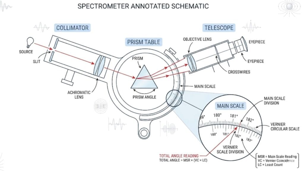
A spectrometer is a precision optical instrument used to study the spectrum of light by measuring the angles at which light is dispersed or diffracted. The basic laboratory spectrometer uses a prism or diffraction grating to separate light into its component wavelengths. By measuring the angle of minimum deviation or the angle of diffraction, the wavelength of light or the refractive index of a prism can be determined with high accuracy.
The instrument consists of three main parts:
- Collimator: Produces a parallel beam of light from a slit source
- Prism table: A rotating circular table with angular graduations, where the dispersing element (prism or grating) is placed
- Telescope: Rotates around the prism table to receive and observe the dispersed light at different angles
Least Count and Range
\[ \text{LC of spectrometer} = \frac{\text{Value of 1 main scale division}}{\text{Number of Vernier divisions on the circular scale}} \]
- Standard LC: 1′ (one arc minute) for a 30-division Vernier on a 0.5° main scale
- Some models: 30″ (thirty arc seconds) for 60-division Vernier
The reading is in degrees and arc minutes (or degrees and fractions of degrees).
How to Read It
Step 1: Read the main circular scale — the last complete half-degree mark before the Vernier zero.
Step 2: Read the Vernier scale — find the Vernier division that coincides with any main scale division. Multiply by the least count in arc minutes.
Step 3: Add main scale reading and Vernier scale reading.
Step 4: Repeat on the second Vernier (diametrically opposite) and average — this eliminates eccentricity error.
What It Is Used For
Refractive index of a prism (using angle of minimum deviation), wavelength of spectral lines (using diffraction grating), verification of Cauchy’s equation, study of emission spectra of elements. The spectrometer is used in Class 12 optics practicals and is the most complex instrument in the standard school lab curriculum.
Common Mistakes
- Not levelling the prism table before starting — an unlevel table gives incorrect angular readings
- Reading only one Vernier instead of averaging both — introduces eccentricity error
- Not locating the minimum deviation position carefully — even a few minutes of arc off gives significant error in refractive index
- Forgetting to convert arc minutes to degrees when reporting angles: 1° = 60′, so 45°30′ = 45.5°
Comparative Summary: All Ten Instruments at a Glance
| # | Instrument | Measures | Standard LC | Range | Connection/Use Type |
| 1 | Metre Scale | Length | 1 mm | 0–100 cm | Direct contact |
| 2 | Vernier Caliper | Length (precise) | 0.1 mm | 0–15 cm | Jaw contact |
| 3 | Screw Gauge | Very small lengths | 0.01 mm | 0–25 mm | Spindle contact |
| 4 | Stopwatch | Time intervals | 0.01 s (digital) | 0–30 min | Manual trigger |
| 5 | Thermometer | Temperature | 0.5°C–1°C | −10°C to 110°C | Immersion |
| 6 | Spring Balance | Force / Weight | 0.1–1 N | 0–50 N | Vertical suspension |
| 7 | Ammeter | Electric current | Varies by range | mA to A | Series connection |
| 8 | Voltmeter | Potential difference | Varies by range | mV to V | Parallel connection |
| 9 | Measuring Cylinder | Volume (liquid) | 0.2–1 mL | 10–1000 mL | Liquid container |
| 10 | Spectrometer | Angles (optical) | 1 arc minute | 0°–360° | Optical table |
Which Instrument for Which Measurement?
This is a practical decision every student must make and the wrong choice costs precision.
Measuring the diameter of a wire: Use the screw gauge. The Vernier caliper cannot resolve the required precision (typically 0.3–1.0 mm) and the ruler is completely insufficient.
Measuring the inner diameter of a test tube: Use the Vernier caliper with the internal jaws. The screw gauge cannot fit inside a tube of this size.
Measuring the length of a pendulum string: Use the metre scale. The length is in the tens of centimetres range, where the ruler’s 1 mm precision is entirely sufficient and appropriate.
Measuring the volume of an irregular stone: Use the measuring cylinder with the liquid displacement method. No length-measuring instrument can handle an irregular shape directly.
Measuring the current through a resistor: Use the ammeter in series. The voltmeter cannot measure current directly.
Measuring the angle of minimum deviation through a prism: Use the spectrometer. The angular precision required (fractions of a degree) cannot be achieved by any other instrument in the standard lab set.
Learn more about How to Find Significant Figures: Rules, Examples & Common Mistakes
Why Instrument Knowledge Matters Beyond the Lab
Understanding your instruments is not a lab skill separate from physics understanding — it is physics understanding. Every measured value you report comes with implicit claims: this is accurate to this precision, this was measured with this technique, this uncertainty arises from this source. A student who knows their instruments can make those claims explicitly and justify them. One who does not is just writing down numbers.
In competitive exams, instrument knowledge appears in two forms. Directly — least count calculations, instrument reading problems, zero error correction. Indirectly — significant figures in computed answers, understanding which error source dominates in a given experiment, knowing why a derived quantity has the uncertainty it does.
Both forms reward the same underlying understanding: knowing what each instrument does, what it can and cannot resolve and how to use it correctly.
Learn more about Top 5 Errors in Physics Measurements and How to Minimize Them
Conclusion
Ten instruments. Ten different working principles. Ten different precision levels and measurement ranges. And one common thread running through all of them — the quality of the measurement depends on the understanding of the person holding the instrument.
A metre scale in careful hands gives better results than a Vernier caliper used carelessly. A thermometer read at the wrong moment is worse than useless — it gives you a wrong number with false confidence. The spectrometer, which is capable of extraordinary angular precision, produces nothing useful if the prism table is unlevel or only one Vernier is read.
Study each instrument until you can explain its working principle in plain language, state its least count without hesitation, describe the reading procedure step by step and name the two or three mistakes most commonly made with it. That level of familiarity is what the lab practical examinations test — and it is what genuinely good experimental physics requires.
Frequently Asked Questions
What is the most precise instrument in a standard physics lab?
Among the ten instruments covered here, the spectrometer has the finest angular least count (1 arc minute ≈ 0.017°) and the screw gauge has the finest length least count (0.01 mm). For length measurement specifically, the screw gauge is the most precise standard lab instrument. Advanced lab instruments like interferometers achieve far greater precision, but these are beyond the standard school curriculum.
Why is the ammeter connected in series and the voltmeter in parallel?
An ammeter must carry the full circuit current, so it is connected in series — the same current flows through it as through the component being studied. It has very low resistance so it does not significantly affect the circuit. A voltmeter measures the potential difference across a component, so it must be connected across it (in parallel). It has very high resistance so almost no current flows through it, which ensures it does not alter the circuit it is measuring.
What is zero error and which instruments are affected by it?
Zero error is a reading offset that occurs when an instrument does not read zero when the measured quantity is zero. The Vernier caliper and screw gauge are the most commonly affected instruments in the standard lab. The spring balance and ammeter can also have zero errors. Always check and correct for zero error before recording measurements.
How do I choose between a Vernier caliper and a screw gauge?
Use the Vernier caliper for objects larger than about 1 mm and up to 15 cm — it handles a wide range and can measure inner dimensions and depths. Use the screw gauge for objects smaller than 25 mm that require precision to 0.01 mm, such as wire diameter or glass thickness. If both instruments can handle the object, the screw gauge is more precise.
Why must a thermometer be read while still inside the liquid?
Mercury expands and contracts very quickly in response to temperature change. The moment the thermometer is removed from the liquid, it begins equilibrating to the surrounding air temperature. The mercury column shifts almost immediately. Reading after removal gives the ambient temperature, not the liquid’s temperature.
What is the reaction time error in a stopwatch and how is it minimized?
Reaction time is the delay between the event occurring and the human operator pressing the stopwatch button — typically 0.1 to 0.3 seconds. This creates a systematic error in every time measurement. It is minimized by timing multiple events (e.g., 20 oscillations of a pendulum instead of 1) and dividing — the reaction time error becomes a much smaller fraction of the total measured time.
Is the spectrometer used in JEE or NEET practical exams?
The spectrometer is part of the Class 12 CBSE practical syllabus and appears in board practical examinations. It is not typically tested in JEE Main or NEET as a hands-on practical, but the concepts it relies on — angle measurement, least count, Vernier reading on a circular scale, refractive index via minimum deviation — do appear as theory and numerical questions in both competitive exams.